Product News _ 노이즈 제거용 3단자 관통형 필터
컨텐츠 정보
본문

Table of Contents
- Basic Configuration of an Input Filter
- Normal (differential) Mode Noise and Common Mode Noise
- Evaluation Conditions for Checking the Effect of Noise Suppression for Each Filter Configuration
- Results After Checking the Effect of Noise Suppression for Each Filter Configuration
- Conclusion
Basic Configuration of an Input Filter
In input line of a DC-DC converter, large noise is generated by the input voltage fluctuations due to the switching noise or Nth harmonics consisting of the fundamental frequency during switching. The noise has two modes: common mode and normal (differential) mode, and so appropriate components must be selected depending on the noise mode.
As shown in Figure 1, during the initial design stage, a π-type filter consisting of capacitors and an inductor (C+L+C) is a desirable pattern configuration for normal mode noise countermeasures. Also, a common mode filter (CMF) is effective for common mode noise countermeasures.

Normal (differential) Mode Noise and Common Mode Noise
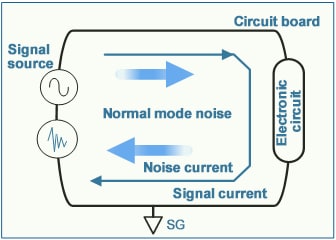
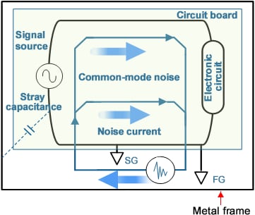
There are two types of conducted noise: normal (differential) mode noise and common mode noise. Normal mode noise is generated between circuit lines and flows in reverse phase, while common mode noise is generated between circuit lines and GND and flows in the same phase. For noise suppression measures, use of appropriate countermeasure components according to the noise mode is necessary.
Inductors and capacitors are typically used for normal mode noise, while a common mode filter is effective for common mode noise.
Noise flowing through the circuit line
(flowing in reverse phase of the line)
Noise flowing through the frame ground
(flowing in same phase of the line)
Evaluation Conditions for Checking the Effect of Noise Suppression for Each Filter Configuration
As the switching frequency of DC-DC converters increases, the noise level in the FM band also increases. Normally, 2-terminal capacitors are used for π-type filters, but further noise suppression can be achieved by using 3-terminal feed-through filters, which feature low ESL. In this guide, we compared and verified the effects of three configurations of π-type filters with the following evaluation contents.
For the conducted noise voltage method, we separated normal mode noise and common mode noise and compared the filter effects. All three configurations were measured using our common mode filter as a common mode countermeasure.
- ■DC-DC converter conditions
Input voltage: 12V
Output voltage: 5V
Switching frequency: 2MHz
Output current: 2A - ■Evaluation Items
1) Transfer characteristics of π-type filter (S21)
2) Conducted noise voltage method
Evaluation Circuit
*Transfer characteristic (S21) analysis by simulator
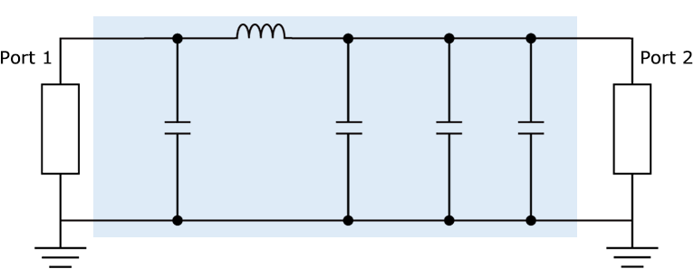
■ Measurement place:3m Anechoic chamber
■ Frequency:150kHz-108MHz
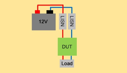
Evaluation Configuration
| π-type filter configuration | Configuration 1: No filter | Configuration 2: Capacitors (2-terminals) | Configuration 3: 3-terminal filters (feed-through filter) |
| Wiring image |  |  |  |
| C1 | - | 3.2mm×1.6mm, 4.7μF,35V | YFF series 3.2mm x 1.6mm,1μF,100V,6A Feed-Thru connection* |
| L1 | - | 2.0mm×1.2mm,220Ω at 100MHz,3A | 2.0mm×1.2mm,220Ω at 100MHz,3A |
| C2 | - | 3.2mm×1.6mm,4.7μF,35V | YFF series 3.2mm x 1.6mm,1μF,100V,6A Feed-Thru connection* |
*For more information on feed-through connection,
please refer to the following link.
Results After Checking the Effects of Noise Suppression for Each Filter Configuration
The verification results of each configuration show the 3-terminal filter (feed-through filter) has a very high attenuation effect in the high-frequency band.
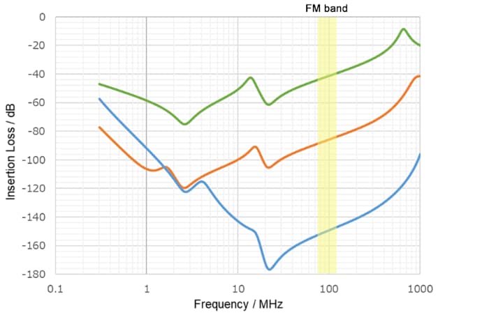
- Configuration 1: No filter
- Configuration 2: Capacitors (2-terminals)

- Configuration 3: 3-terminal filters (feed-through filter)

Typically, the normal mode noise level is greater than the common mode noise level.
For normal mode noise countermeasures, a π-type filter with a 3-terminal feed-through filter is very effective in noise suppression in a wide range of frequency bands, including the FM band.
Normal mode
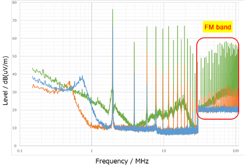
- Configuration 1: No filter
- Configuration 2: Capacitors (2-terminals)

- Configuration 3: 3-terminal filters (feed-through filter)

- *Indicates only peak value.
Common mode

Total (Normal + Common)
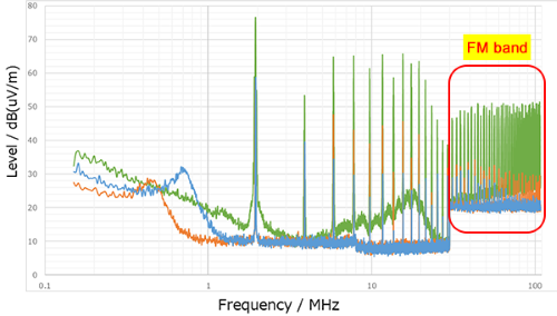
Conclusion
Generally, DC-DC converters generate large high-frequency noise in the input line due to high-speed switching. Therefore, countermeasures against high-frequency noise including FM band are particularly important. In this case, a distinction between normal mode and common mode is important, and appropriate components should be selected according to the noise mode.
Usually, on the input line of a DC-DC converter, the normal mode noise level is greater than the common mode noise level. Therefore, we recommend the configuration of a π-type filter, which is effective for normal mode noise.
Furthermore, the use of 3-terminal feed-through filters for the capacitors of the π-type filter is more effective in high-frequency noise suppression.
관련자료
-
이전
-
다음


